Thank you for using this product. If the appearance or function is different from this manual due to the difference betweeneach product model or version upgrade or other reasons, please refer to the actual product or contact the manufacturer.The contents of this manual will be updated from time to time. Unless otherwise agreed, this manual is intended as a guide for use only. All statements, information and recommendations contained in this manual do not constitute a warranty of any kind, express or implied.
Version description
This manual is applicable to 4CH 1080P HD vehicle-mounted DVR products, which may not be accurately described in some technical details and appear in real objects In case of any inconsistency with this manual,refer to the actual product or consult the technical support of the manufacturer. The contents of this manual will be updated irregularly without notice.
Precautions for use
Caution:
- In order to ensure that the device will not be damaged accidentally during transportation,please handle the them with carefully.
- All installation and maintenance must be carried out by qualified personnel with professional training.
- This product cannot be installed on the vehicle where it has been eroded by rain or other liquids for a long time.
- The installation method and all materials must be able to bear the weight of the fuselage.
- In order to prolong the service life of the device, please keep the equipment away from heat source, dust and strong magnetic field.
- In order to ensure the normal heat dissipation of the device, no heavy objects shall be placed above the device, and no sundries shall be stacked within 15cm around the device.
- Do not flush the equipment directly when cleaning the vehicle.
- The output power of the equipment shall not be connected with any non recommended devices.
- Do not try to put fingers or other external matters into the gap of the device when the it is running.
- Do not open or disassemble the device without the guidance of a professional.
- It is not allowed to replace any module or connect other external equipment when the host is electrified.
- This device adopts 12V-36V DC power supply. Please pay attention to the positive and negative poles when wiring, to avoid short circuit.
1. Product Introduction
Product Overview of Vehicle – Mounted HD Hard Disk Video Recorder
This product is a vehicle – mounted HD hard disk video recorder with 4 – channel analog audio and video recording, playback, and network functions. It uses a DSPS ARM dual – core processor and Linux embedded OS, integrating H.264 video codec, 3G/4G, GPS/BD, and WIFI tech. It records driving info, uploads via wireless, and with center software, enables central monitoring, alarm linkage, and playback analysis based on the central database.
1.1 Product Features
- Adopts H.264 encoding for high compression, clear images, and less disk space.
- M4 connector for video interface, reliable and anti – seismic.
- UPS power – off protection, runs 3 – 8 secs on sudden power cut to protect files.
- Uses Micro SD and hard disk for storage, easy data access.
- Supports HDMI, VGA, and CVBS video output.
- Supports 1TB SD and 4TB hard disk.
- +8V~+36V wide voltage, suitable for all vehicles.
- 4 – channel 12V / 0.5A power for peripherals.
- 4 – channel alarm input.
- RJ45 Ethernet, RTSP, LAN real – time preview.
- Built – in 3G/4G, GPS, WiFi (optional 5.8ghz dual – antenna WiFi).
- Professional playback software for synchronized track, state, speed, and AV playback.
- Centralized management software for real – time image and alarm info transmission.
1.2 Platform Download Address and Login Interface
- Mobile: Search “CMSV7” in app store to download.
- PC: Copy http://119.23.207.22/808gps/login.html, open in browser, download Windows version or directly log in.
- Open CMSV7, enter device label info and click “Login” to access platform.
2. Product Specification
2.1Front panel Definition
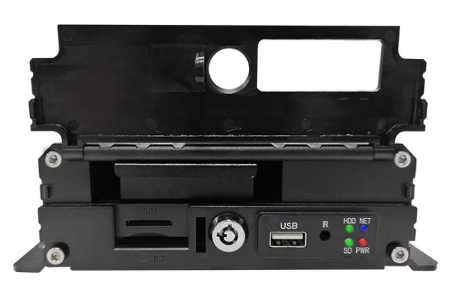
2.1.1 LED Indicator and Status Description
- 【PWR】Power Input Status Indicator: The light is illuminated to signify that the system power supply is functioning properly.
- 【SD, HDD】SD Card and Hard Disk Drive Work Indicator: A steady – on light indicates that the SD card or HDD is operating normally. When the light is off, it means that there is no SD card or HDD inserted, or the SD card or HDD is malfunctioning.
- 【NET】Network Indicator: When the registration is successful, the network indicator lights up. If the device is not registered or the registration fails, the network indicator remains off.
2.1.2 Other Interface Descriptions
- 【Panel Lock】: Controls device power on/off. Locks the SD card during boot to prevent improper insertion or removal.
- 【SD, HDD】: SD card and 2.5” HDD slots for data storage.
- 【SIM】: 3G/4G phone card slot for mobile network access.
- 【IR】: Receives infrared control signals for remote operation.
- 【USB Interface】: Used for system backup and upgrade.
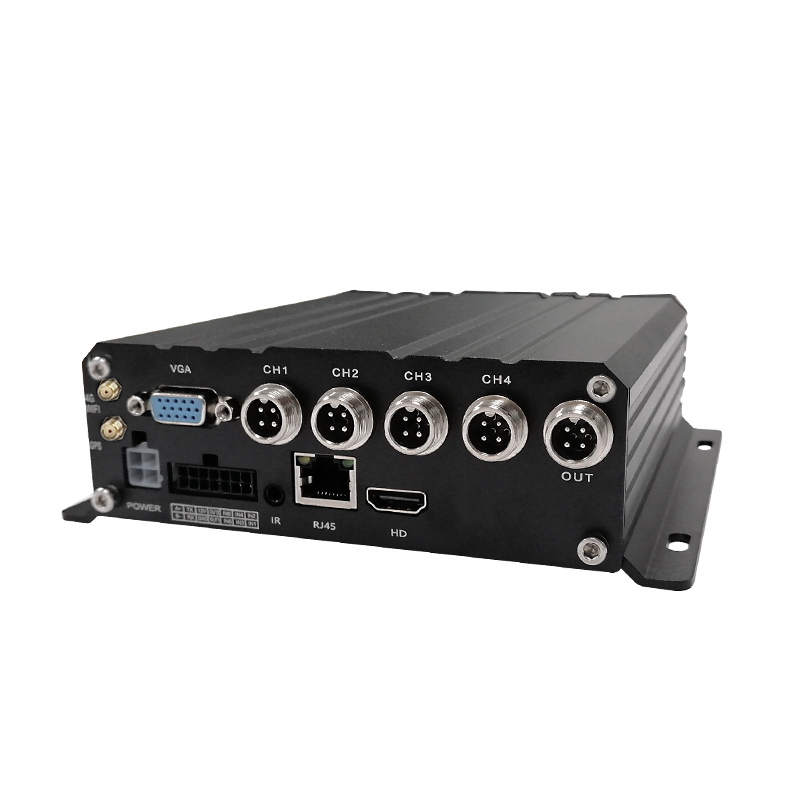
2.2Rear panel definition
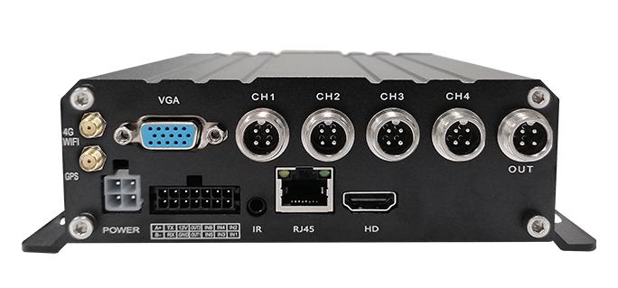
2.2.1 Interface Demonstration
- 【POWER】: Power interface, connect to the power source for power supply.
- 【VGA】: VGA high – definition video output, connect to external display devices.
- 【I/O】: 4 alarm inputs, 2 outputs, 1 12V positive, 1 GND negative, 1 RS232 and 1 RS485, used for signals and communication.
- 【IR】: Infrared extension line interface, expand the range of infrared signals.
- 【RJ45】: Ethernet interface, enable wired network connection.
- 【HD】: HDMI high – definition output, transmit high – definition audio and video.
- 【CH1 – CH4】: 4 – channel camera interface, can connect 4 cameras.
- 【OUT】: Audio and video output, can select audio or video.
- 【WIFI】: WIFI antenna interface, connect the antenna to connect to the wireless network.
- 【4G/5G】: 3G/4G/5G antenna interface, access to mobile networks, can choose WIFI or 4G.
- 【BD/GPS】: GPS/BD antenna interface, connect the antenna to obtain positioning.
2.2.2 Definition of host aviation interface

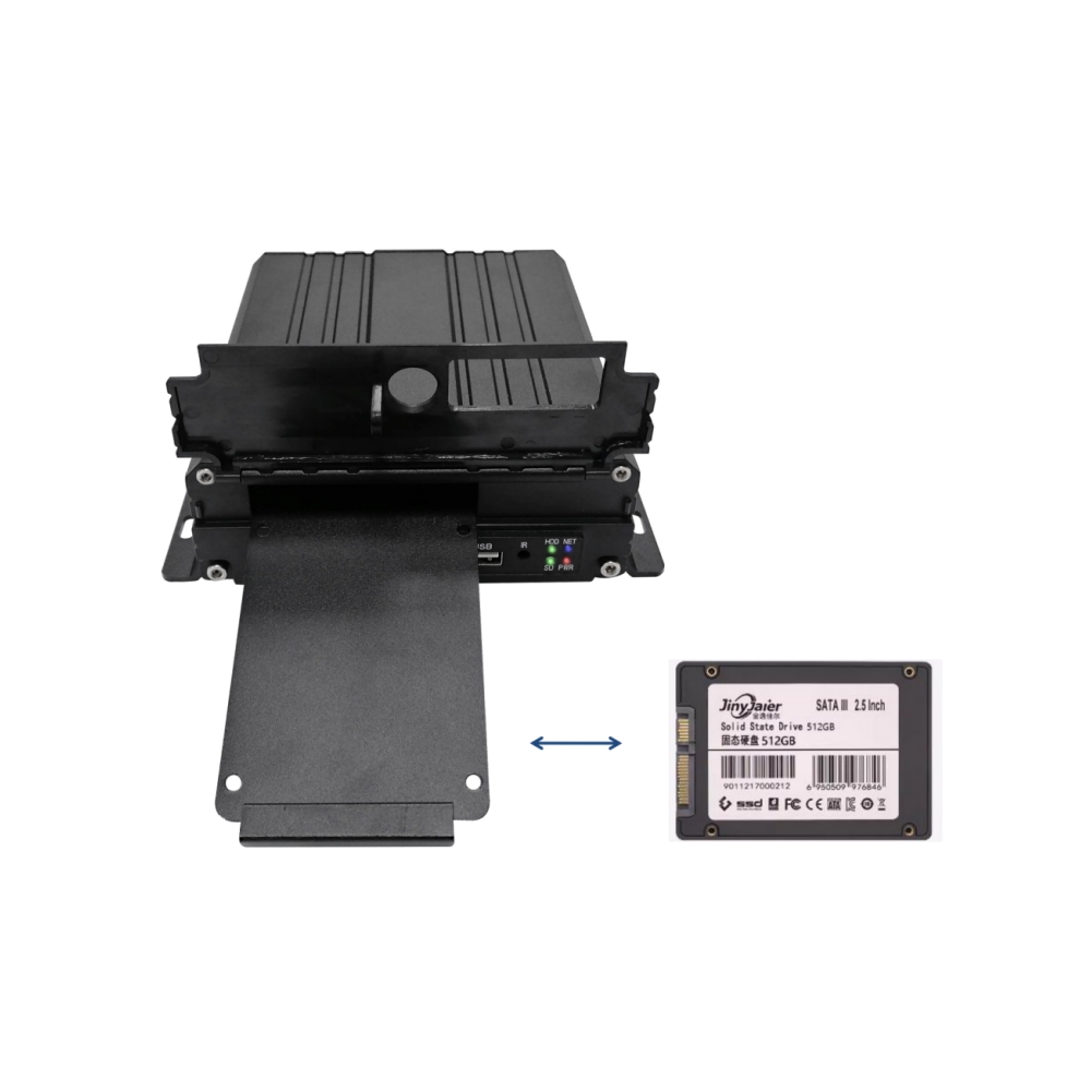
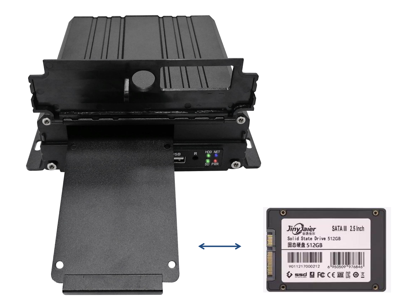
2.2.3 Hard Disk Installation Instruction
- First Step: Remove the hard disk box (as shown in Figure 1).
- Second Step: Insert a 2.5 – inch hard disk with the SATA interface facing outwards (as shown in Figure 2), and fasten the fixing screws on the back (as shown in Figure 3).
- Third Step: Insert the hard disk box back into the device and tighten the screws on the hard disk box (as shown in Figure 4).
3. Accessory
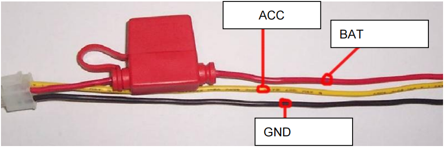
3.3.1 Cable Instructions
As shown in Figure 5, the POWER cord has a multi – colored plug at one end, which is connected to the [POWER] 4PIN connector on the rear panel of the device. The red and black wires are directly connected to the car battery. The red wire is connected to the positive terminal, and the black wire is connected to the negative terminal. The yellow wire is connected to the live wire. After the car key is turned on, the host equipment automatically powers on; after the car key is turned off, the host equipment automatically powers off.
Precautions:
- Before connection, it is necessary to confirm that the voltage of the car battery is between 12V and 36V. If used for a long time under conditions outside this range, the device will be damaged.
- After connecting the cables, pay close attention to the insulation between the power cables to prevent the power cables from short – circuiting and burning the battery.
- The red wire must be connected to the positive line of the battery. Otherwise, the device will not support delayed shutdown, and the last recorded video will be lost.
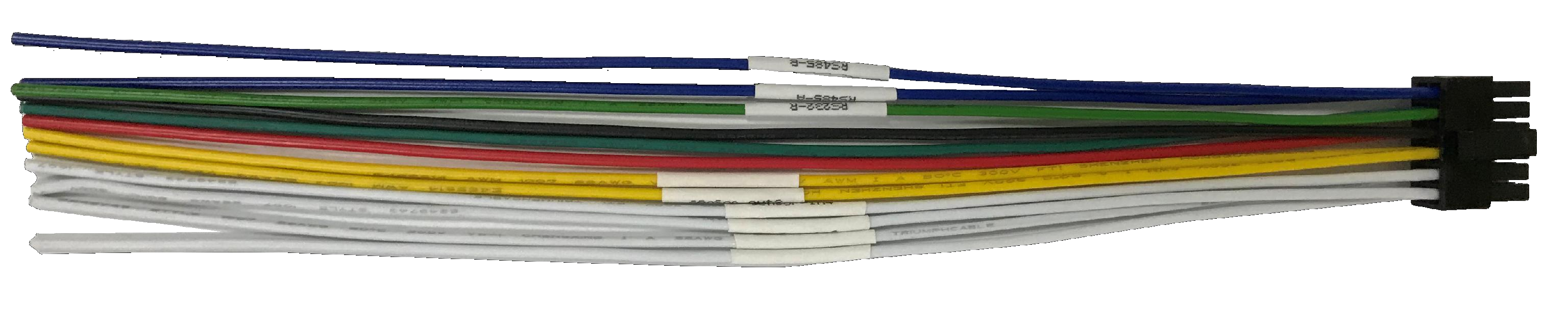
3.3.2 I/O Alarm Input and Output
Figure 2 shows the I/O interface cable connected to the [I/O] 12PIN connector on the device’s rear panel.
There are 4 alarm input channels to receive signals from external sensors in real – time. Once abnormal signals are detected, the device acts per pre – set procedures.
Two alarm output channels send signals to warning lights or alarms when the device detects an issue. Proper configuration of these functions strengthens the device’s monitoring and response capabilities, ensuring system stability.
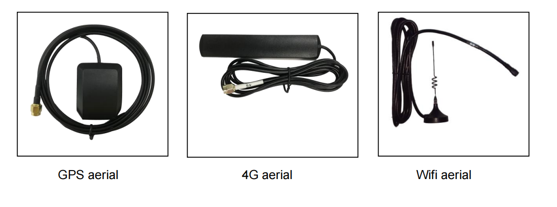
3.3.3 Installation of GPS, 3G/4G/5G, and WIFI Antennas
As shown in the figure below, the GPS, 3G/4G/5G, and WIFI antennas should be connected to their respective positions on the rear panel of the MDVR. After connection, ensure proper cable routing to minimize external signal interference. This way, the antennas can function optimally and maintain stable signal reception.